Here are some bits of information that have proved useful during my build of the “MOD 800 2204 Small Box kit – 50w Output – Master Volume British Amp Kit” from Modulus Amplification, a UK-based amplifier kit supplier. You can find the kit here.
20/11/2021 Update – I should have edited this page ages ago. In the previous version I mentioned I’d had issues with the kit with the amp lacking gain. The issue turned out to be a resistor with the wrong value. The supplied R1 was 270K rather than the required 2.7K. I always check component values with a multi-meter but because the digits were the same I didn’t spot the error. Lesson learned! Michael from Modulus spotted the error for me.
The final amp turned out great. Video of the result can be found here:
Warning!
There may well be errors in my diagrams! I strongly advise you verify everything yourself and treat this resource as a guide only. If you spot any mistakes please leave a comment and I’ll make the necessary corrections.
Mapping the Modulus layout to a real schematic
I worked to the following schematic:
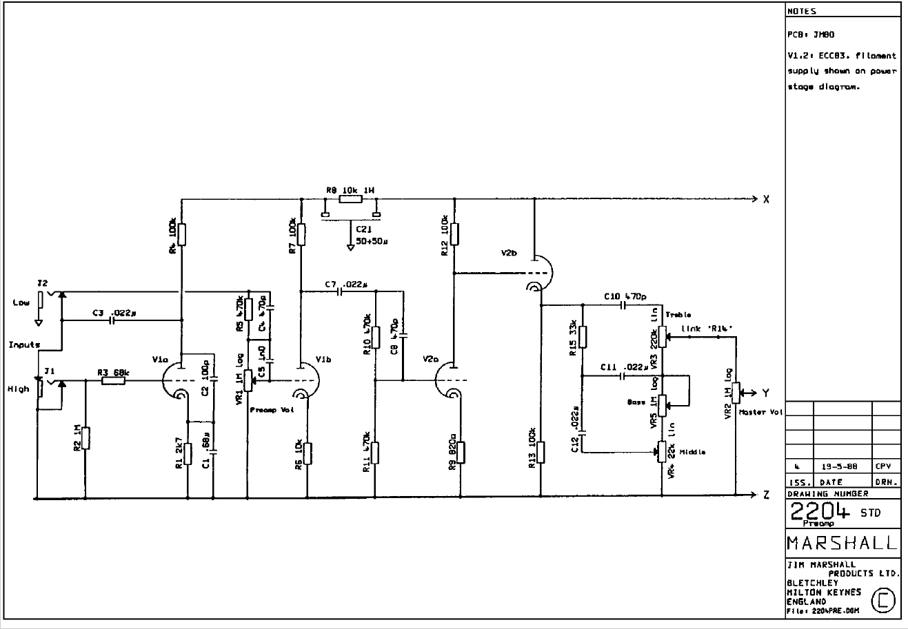
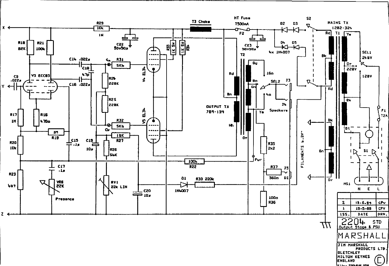
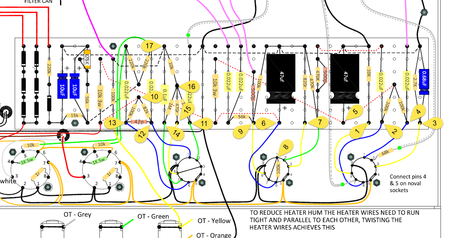
Given that schematic, I tried to identify the component numbers on the Modulus layout as follows:
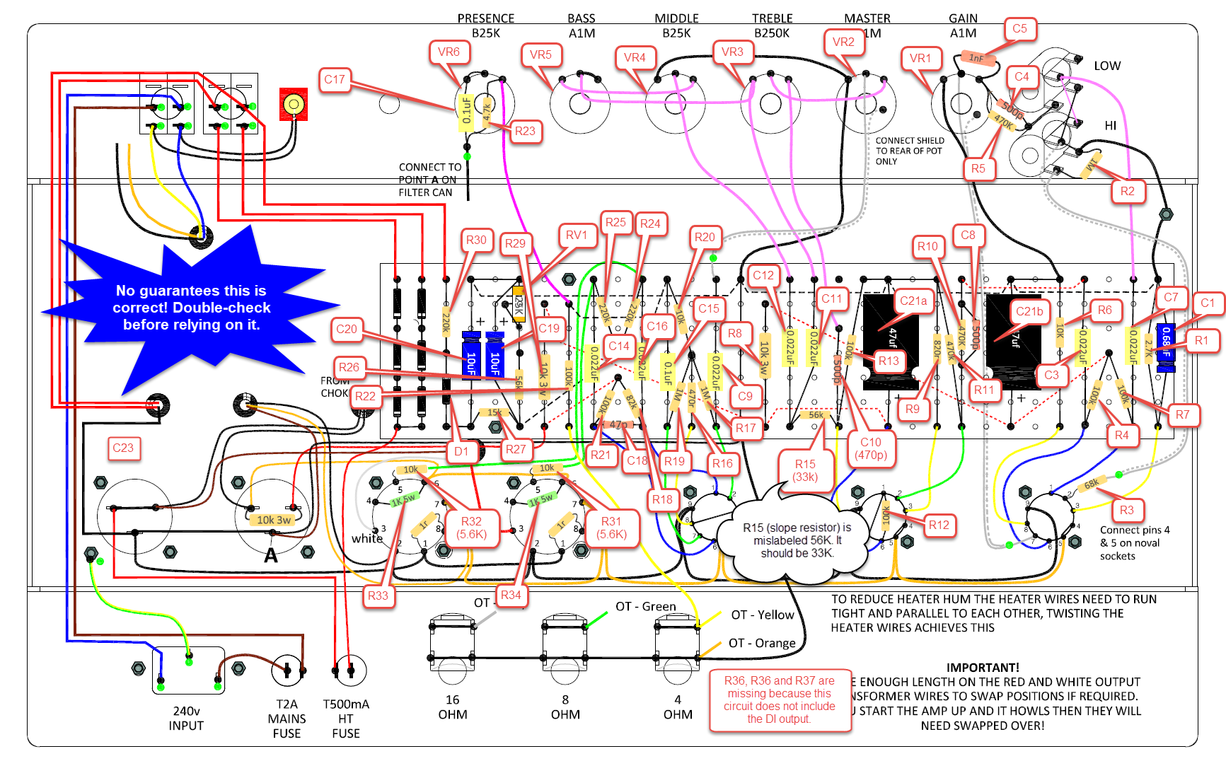
At the time of writing there is definitely one correction that should be made to the Modulus layout. R15 is given as 56k. That’s wrong as it should be 33K. This is the slope resistor and it affects midrange. I believe Plexis used 56k but the JCM 800 used 33k. I also believe a possible mod is to use 47k for a beefier midrange (Soldanos reportedly use 47k).
A quick note here about C2. You’ll notice it’s missing from the Modulus kit. C2 should be a 100pf disk capacitor that sits between the plate and the cathode (pins 1 and 3 I believe) of the first preamp tube. This cap was actually missing on older circuits and added later so I guess that’s why it’s missing here. My understanding is that if you intend to mod the amp to add more gain, you might want to consider adding a 100pf 600v+ ceramic disk cap.
20/11/2021 Update – I added the C2 cap mentioned above because I modded my amp (Rob Robinette’s cold clipper mod). I couldn’t hear any discernible difference with this cap added even when the mod is switched off.
Marshall JCM 800 Service Manual and the Modulus layout
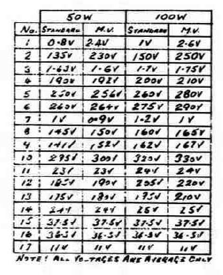
I found a PDF of the old “Marshall JCM 800 Service Manual” which included some example voltages at various test points in the preamp circuit. Here’s the schematic with the points labelled 1 to 17:
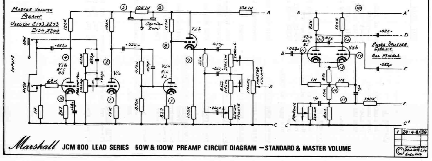
And here’s the voltage data associated with those test points as found in the service manual:
And then for good measure, here’s the test points on the Modulus layout (as well as I could identify them):
Rob Robinette’s useful information
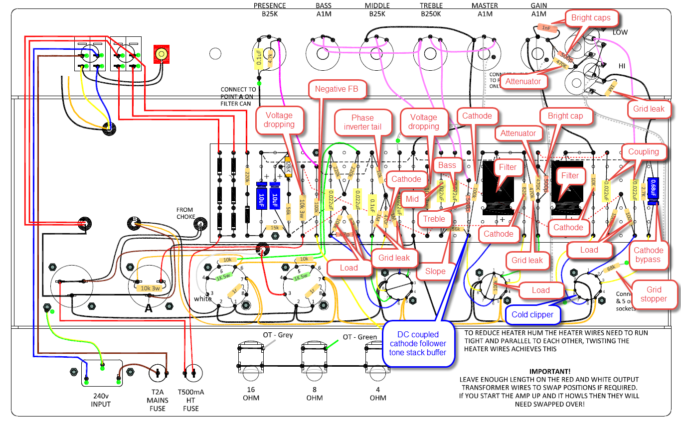
Rob Robinette has a great page explaining how a JCM 800 works. I thought it would be interesting to map some of Rob’s information about component names and voltages to the Modulus layout. In general, the 0.022uf capacitors are going to be coupling caps. I didn’t bother to label most of those. This is what I ended up with:
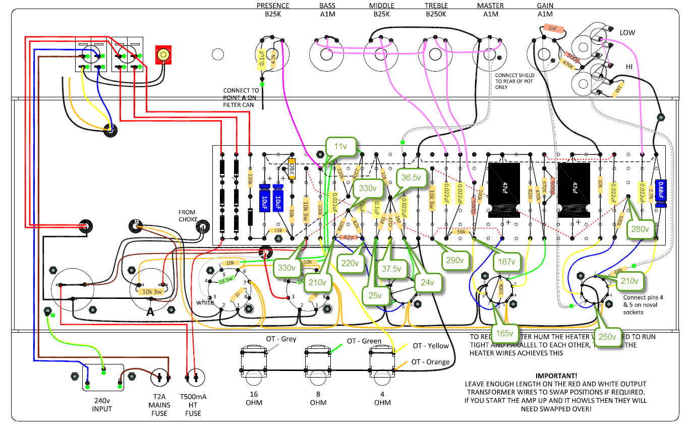
NB: Usual caveat here. I did my best to get the voltages in the right places but errors are likely. Double-check yourself!
Just finishing mine off, and your notes helped actually. I spotted the issue with the 2.7k resistor, but was wondering where the hell the 33k resistor went. Luckily your notes were clear and highlighted it. Cheers
Glad to be of help!
i turned my amp on last weekend and it sounded awful and then howled at me after a few minutes of being on. Just went through everything with a fine tooth comb and everything was as it should be. Changed the red and white transformer cables round and bingo. It sounds amazing Andy. Will try and get a video of it up next week and compare it to my studio head for you
Brilliant Ed. Pleased to hear you got it running. I have to say, the Plexi went into positive feedback and howled as soon as it was switched on so I knew immediately I had to swap the OT wires over. The JCM800 acted differently and did the same as you; it took a few minutes before a high-pitched squeal manifested itself. Looking forward to the hearing yours!
Great build, the wiring looks really good and the sound is great. Thumbs up… by the way, what diodes did you use? 1N4007 as in the original circuit or 1N5408?
Cheers
Hi George. Thanks for the comment. In answer to your question I actually do not know and/or can’t remember! It’s a kit build so it would be whatever came with the kit. I went for upgraded caps and pots but diodes weren’t changeable. I’m sure Modulus could advise is you really want to know. All the best!